THE ATMOSPHERIC VORTEX ENGINE (AVE) IN PERSPECTIVE
The Atmospheric Vortex Engine (AVE) is proposed as a device for producing mechanical energy by means of artificially generated vortex. The aim is -by generation an artificial vortex - to eliminate the physical chimney that is essential for operating a Solar Updraft Tower (SUT) and thereby reducing investment capital.
PRINCIPALS
The AVE has the same thermodynamic idea as the Solar Updraft Tower (SUT).
Both designs use the buoyancy of warm air that is centralized to cause updraft.
Major difference : the AVE design has no chimney.
Solar Updraft Tower (SUT) in a nutshell
A SUT solar chimney consists of a tall vertical tube (chimney), an transparent solar collector surrounding the base and a turbine located at the inlet of the tube. The SUT is using the naturally occurring heat content of surrounding air and centralizes its buoyancy in to the chimney. The updraft draws in more air.
Atmospheric Vortex Engine (AVE).
The AVE however uses the controlled characteristics of tornadic air displacements instead of a chimney. This chimney consists out of buoyant air that is flowing in a circular motion around the centre called a vortex.
The physical chimney is to be replaced by a centripetal swirling upward airflow called the vortex. A traditional Solar Updraft Tower (SUT) can be defined as a low temperature solar thermal power plants that uses the atmospheric air as a working fluid. (Fig.1) [1] [5]
Air is heated as a result of the greenhouse effect under a transparent roof (solar collector). Because the roof is open around its periphery, the buoyancy of the heated air draws a continuous flow from the roof perimeter into the chimney (updraft tower). A turbine is set in the path of the air current to convert the kinetic energy of the flowing air into electricity. [2-6]
Many enhancements of Solar Updraft Tower (SUT) plants have been proposed and researched. Alternative approaches to enhance the performance of solar chimney power plants are the hybriding the solar operation mode [7]
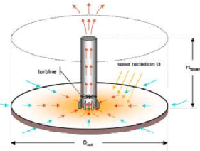
Figure 1: The main features of a solar chimney power plant; solar collector, updraft tower and turbine.
DOWNSIDE OF THE SOLAR UPDRAFT TOWER (SUT)
One of the factors influencing the heat to work conversion efficiency of a SUT solar chimney is the height of the chimney.
- The efficiency is directly proportional to its height.
- The height is directly proportional to the:
- cost of investment,
- maintenance and operating costs
BACK GROUND OF VORTICES
A well-known form of an vortex is the tornado. The tornado is a highly effective mechanism through which Nature acts to convey humid boundary layer air to the top of the troposphere where precipitation is initiated and where it interacts with the stratosphere (fig.2) [8]
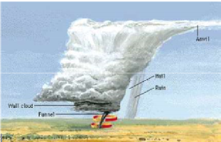
Figure 2: Vortices in nature.
The troposphere is the lowest region of the Earth's atmosphere, where masses of air are mixed together and the temperature decreases with altitude. The air is heated from the ground up because the surface of the Earth absorbs energy and heats up faster than the air. The heat is mixed through the troposphere because on average the atmosphere in this layer is slightly unstable.
The vortex engine is basically a system to enhance the transmission of energy through the troposphere. [8]
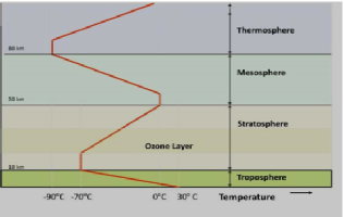
Figure 3: Simplified graph of atmospheric temperature profile [8].
CONVECTIVE VORTICES GENERATION
Convective vortices are common features of atmospheres that absorb lower entropy-energy at higher temperatures than they emit higher-entropy-energy to space. These vortices range from small to large-scales and play an important role in the vertical transport of heat, momentum, water vapours and condensation particles. [9]
SIMULATIONS, NUMERICAL AND COMPUTER FLUID DYNAMICS
Visual Simulations
A method for visual simulation of gaseous phenomena -based on the vortex method- was presented by Park and Kim [10]. This method describes a total vortex flow field by using -localized vortex flows as basic building blocks – and combining them together. Resulting in computational Efficiency Vorticity Equation that van describes as below:
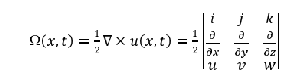
Various boundary conditions were resolved. By exploiting the panel method, the no-through boundary condition in a Lagrangian way is satisfied. [10]
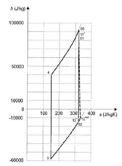
Concentration and stratification of moist heated air on ground level can create a Gravitational Vortex Column. (GVC) A numerical solution was given in a characteristic case, with a GVC process as a part of the cycle. It showed similar to the Brayton cycle obtained in a gravitational field. Typical integration results are shown by a characteristic numerical example of a GVC (as a part of a cycle) in the form of a Mollier h-s diagram. (Fig 4) [11]
Numerical simulations
A method for numerical simulations of vortices with various geometries and operating conditions were performed to study the natural vortex length in CFD code Fluent 6. 1..
A prediction model of the natural vortex length was obtained based on response surface methodology by means of the statistical software program (Minitab V14).
Amongst other than the factors mentioned in publications the results showed that the inlet velocity, and insertion deepness also play an important role in influencing the natural vortex length.
Compared with some experimental conclusions, the results indicate that the present prediction model can estimate the effects of different geometries and operation conditions on the vortex performance more accurate than other models. [12]
The Rayleigh number of generated stable vortices defines the correlation between the buoyancy and viscous forces, for different thermal modes. This criterion was determined as below equation:
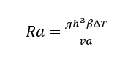
[13]
Most updraft properties were predicted and explain how work of buoyancy is dissipated by use of the model of one-dimensional thermodynamic entrainment-detrainment.
Mechanical energy is produced when heat is carried upward by convection in the atmosphere. Processes for controlling and concentrating where the mechanical energy is produced could be a method of harnessing solar energy.
A process for producing and controlling a tornado-like vortex and thereby concentrating the mechanical energy where it can be captured is proposed. The work produced when air rises from the bottom to the top of the troposphere is typically 1500 J/kg, about the same as the work produced when a kilogram of water is lowered 150 m. [14-17]
ATMOSPHERIC VORTEX ENGINE
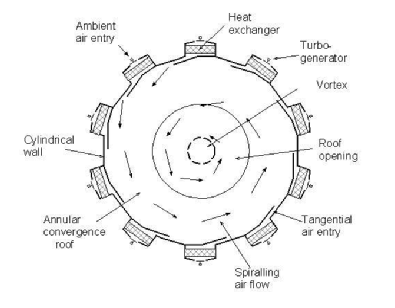
An atmospheric vortex engine (AVE) is a device for producing mechanical energy by means of a controlled tornado-like vortex. The vortex is produced by admitting air tangentially at the base of a circular wall which produces a convective vortex that acts as a dynamic chimney.
The vortex is started by temporarily heating the air near the centre of the station with fuel or steam. The operation of AVE is based on the facts that the atmosphere is heated from the bottom and cooled from the top and that more mechanical energy is produced by the expansion of a heated gas.
An embodiment of the vortex engine is shown in figures 5 and 6. [18] Atmospheric vortex engine has the same thermodynamic basis as the natural draft cooling tower.
The total energy equation is used to calculate the energy received and produced in each process:
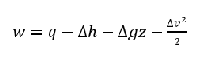
Where w is the work given up, q is the heat received, h is the enthalpy of the air including the enthalpy of its water content, g is the acceleration of gravity, z is the height, and v is the velocity [18].
LOUIS MICHAUD INVENTOR
Louis M. Michaud gets the United States Patent for the design of atmospheric vortex engine with Patent No: US 7,086,823 B2 in August 2006. [19]
Numerical simulation of this atmospheric vortex engine was performed by the CFD analysis of a model-scale Atmospheric Vortex Engine (AVE). The results show that the AVE can generate a vortex flow in the atmosphere much above the AVE and the vortex acts as a physical chimney limiting the mixing of surrounding air into the raising plume of hot air.
A parametric study was conducted and provides a good starting point for future designs. For a given geometry, the physical parameter ‘T’ (temperature difference between the inlet air to AVE and ambient air) is the main parameter that controls the strength of the vortex and in turn the power output.
The full scale simulations subjected to cross wind show that the power generation capacity is not affected by the cross winds. The current full scale simulations do not consider actual temperature gradient present in the atmosphere.

Figure 7 show the contour plot of the tangential velocity in the YZ plane and the vector plot of velocity magnitude at Z =0.4m plane (at the exit of AVE).
It can be seen from these plots that a tornado like vortex flow was generated inside the AVE and the flow extended into the atmosphere till the top of the domain. [20]
REFERENCES
[1] Ninic N, Available energy of the air in solar chimneys and the possibility of its ground-level concentration, Solar Energy, 80: 804-811,2006
[2] Schlaich J., Schiel W, Friedrich K, Schwarz G, Wehowsky P, Meinecke W, et al., The solar chimney: transferability of results from the Manzanares solar chimney plant to larger scale-plants, Tech. Rep., Schlaich Bergermann und Partner CEs, Stuttgart; 1995.
[3] Koonsrisuk A., S. Lorente, A. Bejan, Constructal solar chimney configuration, International Journal of Heat and Mass Transfer, 53: 327-333, 2010.
[4] Schlaich J., R. Bergermann, W. Schiel and G. Weinrebe, Sustainable Electricity Generation with Solar Updraft Towers, Structural Engineering International, 2004.
[5] Schlaich J., R. Bergermann, W. Schiel, G. Weinrebe, Design of commercial solar updraft tower systems-utilization of solar induced convective flows for power generation, Solar Energy Engineering 127: 117-124, 2005
[6] Xinping Zhou, Fang Wang, Reccab M. Ochieng, A review of solar chimney power technology, Renewable and Sustainable Energy Reviews, 14: 2315-2338, 2010.
[7] Aja Ogboo Chikere, Hussain H. Al-Kayiem, Zainal Ambri Abdul Karim, Review on the Enhancement Techniques and Introduction of an Alternate Enhancement Technique of Solar Chimney Power Plant, Journal of Applied Sciences, 11 (11): 1877-1884, 2011.
[8] Donald Cooper MIEAust, Reaping the Whirlwind: The atmospheric vortex. University of Wisconsin-Milwaukee 2012
[9] Niltono O, Renno, a thermodynamically general theory for convective vortices, University of Michigan. Tellus 60A 688-599, 2008.
[10] Sang Il Park, Myoung Jun Kim, Vortex Fluid for Gaseous Phenomena,
Eurographics /ACM SIGGRAPH Symposium on Computer Animation 2005.
[11] Ninic N., S. Nizetic, Elementary theory of stationary vortex columns for solar chimney power plants, Solar Energy 83: 462-476, 2009.
[12] Fuping Qian, Mingyao Zhang, Study of the natural vortex length of a cyclone with response surface methodology, Computers and Chemical Engineering 29: 2155-2162,2005.
[13] Varaksin A.Y., M.E. Romash, V.N. Kopeitsev, M.A. Gorbachev, Experimental study of wall-free non-stationary vortices generation due to air unstable stratification, International Journal of Heat and Mass Transfer, 55: 6567-6572, 2012.
[14] Navarro M.C., H. Herrero, Vortex generation by a convective instability in a cylindrical annulus non-homogeneously heated, Physica D, 240: 1181 1188 2011.
[15] Michaud L.M., Thermodynamic Cycle of the Atmospheric Upward Heat Convection Process, Meteorology and Atmospheric Physics, 72: 29 46, 2000.
[16] Michaud L.M., Entrainment and detrainment required to explain updraft properties and work dissipation, Tellus, 50A: 283-301, 1998.
[17] Michaud L.M., Vortex process for capturing mechanical energy during upward heat-convection in the atmosphere, Applied Energy, 62: 241 251 , 1999.
[18] Michaud L.M., The Atmospheric Vortex Engine, IEEE, TIC-STH, pp. 971 975, 2009.
[19] Louis M. Michaud, The Atmospheric Vortex Engine, United States Patent No.: US 7,086,823 B2, Aug. 8, 2006.
[20] Diwakar Natarajan, Numerical Simulation of Tornado-like Vortices, (Chapter 5), Ph.D. Thesis, the University of Western Ontario, Canada, 2011.